


DRIVE BASE
The drive base allows the robot to traverse the field quickly and with great amount of agility. With these criteria, we have chosen to build a Swerve Drive System.
Custom SDS Mk4n & Mk4i Swerve Assemblies
-
L2+ drive reduction (18ft/s) with 4" Thrifty Spiky Wheel Treads
-
Enclosed casing allows for retention of grease prolonging life of mechanisms
Chassis
-
27" x 27"x 20.5" Frame
-
1/8" thick belly pan
Bumpers
-
0.625" Birch Plywood Backing
-
Stacked 0.5” Polyethylene Foam to 2.5” total thickness
-
Density @ 1.74 lb/cu. ft


INTAKE
The intake grabs fuel from the ground and feeds them into the indexer.
Structure and Deployment:

-
Lexan side plates hold the assembly together at 0.375” thickness for both
-
Flexibility under collision and good impact strength to weight ratio
-
2"x1" Crash Bar to help protect drive axels and improve durability
-
A Kraken X60 is used to deploy the intake forwards
-
Geared with MAX Planetary gearboxes at a 60:1 ratio
Fuel Intake
-
2” TPU compliant wheels intakes the fuel along a 25" span.
Bottom kicker roller helps guide fuel up towards the inside of the robot. -
Bottom roller is a 1.5" polycarbonate tube wrapped with Cat Tongue Grip Tape
-
Intake propulsion is geared to a 3:1 gearing powered by a Kraken X60 at a 3:1 ratio
INTAKE REBUILD
We decided to reconfigure our architecture to allow for a linear extension intake. This allows for an improved packaging and reduction of weight. It also allows for a proper hopper system to be simply attached to the robot.

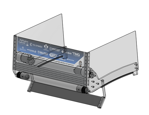
INDEXER
The Indexer agitates and aligns the fuel contained in the robot’s internal hopper and feeds them in a consistent stream into the Feed Tower.
Structure and Indexing:
-
A central column allows for fuel to be continously agitated inside of the hopper. Its conical shape allows for fuel to fall into the indexing line.
-
Walls and funnel structure are 3D printed PLA specifically configured to optimize strength, weight and fabrication time.
-
Moving floor covered with Cat Toungue grip tape allows for fuel to be consistently transferred through the mechanism.
Index line holds 7 fuel.
-
Mechanism is powered by a single Kraken X60 on an 8:1 gearing.


FEED TOWER
The Feed Tower is a collum on the robot that feeds incoming fuel from the Indexer into the Turret/Shooter mechanism.
Structure and Feeding:
-
A set of vertically stacked wheels help guide and push the fuel into the Feed Tower
-
3D Printed Ramp guides the fuel through a transition zone.
A set of two-sided kicker wheels push the fuel up the tower into the turret. -
Geared to a 1.5:1 gear reduction
-
Single Kraken X60 powers mechanism

FEEDER REBUILD
We decided to reconfigure our architecture to shift the feeder inlet 90deg. This shifts the vector of the fuel path away from the vector of the intake, a faster mechanism. This helped reduce the likelihood of the fuel flowing into a jam point.


TURRET
The shooter is a double wheel shooter mounted on a turret with an adjustable hood. The goal is to have a shooter that can adjust to the “shooting on the move” software concept. Doubling the wheels minimizes the Magnus effect by reducing the spin of the ball to zero during flight.
Shooter
-
3" Stealth Wheels on the lower drive shaft
-
2" Stealth Wheels on the upper drive shaft
-
Upper and Lower wheels are geared to a 1:1.5 ratio to match surface speed and minimize Magnus Effect.
-
Both drive shafts are coupled and powered by 2x Kraken X60s
-
Hood adjustment is with a Kraken X44

Swivel Rotation
-
Turret swivel is powered by a Kraken X60 on a 60:1 gear reduction
-
3D Printed Herringbone Gears help minimize backlash
-
A 1:5 (final stage reduction) planetary stack transmits rotational position to a Throughbore Encoder for controls

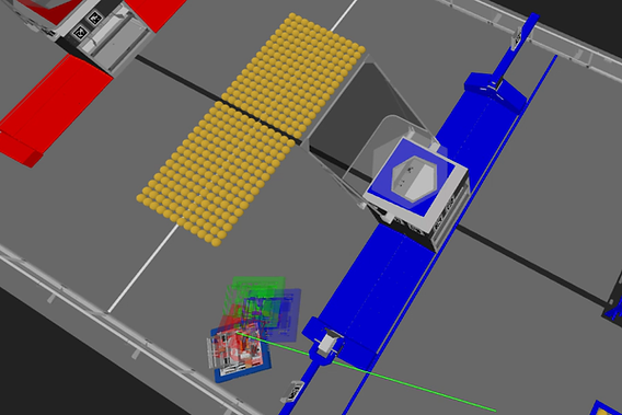
SOFTWARE


-
This year’s codebase focused heavily on building a powerful, realistic simulation environment. Using tools like CTRE Phoenix 6, PhotonVision, and a physics/SOTM solver, the team simulated motors, vision (AprilTags), and automated shooting. This allowed nearly all features—like shoot-on-the-move, localization, and autonomous routines—to be tested and refined in AdvantageScope before running on the real robot, saving significant time and catching errors early.
-
The codebase was built on AdvantageKit, enabling log replay for advanced debugging and optimization while leveraging existing high-quality implementations instead of rebuilding from scratch.
A key design choice was flexibility: using a Factory Method pattern with IO abstraction, the code can seamlessly switch between simulation and real hardware (or even different vendors) without changes to core logic. Combined with extensive logging and tuning through AdvantageScope, this results in a clean, adaptable, and highly efficient system that supports rapid iteration, troubleshooting, and future hardware changes.